
Like the information, please donate to support hosting.
My Old Blog: Pixie 2 CW Radio
June 9th, 2013 | Comments | Share
Tags : blogger pixie 2 amateur radio electronics morse code
Here is a copy of my 3rd post on Blogger, posted on 30th January 2011!
Amateur Radio - Easy to Build Pixie 2 CW Transceiver
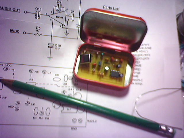
The Pixie 2 is a easy to build, cheap CW (Morse Code) Transceiver. The frequency is determined using a crystal.
The Pixie 2 appeared in the NorCal QRP Club Newsletter on Page 47, Vol.1, #3. It is an outgrowth of RV3GM's similar circuit published in the UK QRP Club, G-QRP Newsletter, "Sprat"
The circuit is simple! It has a two transistor transmitter, using 2N2222 transistors. The oscillator transistor is always going, it supplies injection for the direct conversion receiver, and the first stage of the transmitter. An LM-386 integrated circuit provides the audio output that will drive a small speaker or headphones. The output circuit is a pi type with #26 wire wound around a T-50-2 torroid. This output network becomes the front-end L/C of the receiver. The output of the transmitter is about 250 milliwatts. 3.5 or 7.0 mhz versions may be built.
Components
Exact Values for QRP Frequencies.
Band CW SSB
---- --------------- ----------------
160 1.810 1.910
1.843 (Europe)
80 3.560 3.985
3.710 (Novice) 3.690 (SSB EU)
40 7.040 7.285
7.030 (Europe) 7.090 (SSB EU)
7.060 (Europe)
7.110 (Novice)
30 10.106
20 14.060 14.285
17 18.096
15 21.060 21.385
21.110 (Novice) 21.285 (SSB EU)
12 24.906
10 28.060 28.885
28.110 (Novice) 28.385 (Novice)
28.360 (SSB EU)
6 50.060 50.885
50.285 (SSB EU)
2 144.060 144.285
144.585 (FM)Both filter caps (C6 & C7) are the same.
Values are for CW operation.
160m =4.4 uH, .00176 uF
80M = 2.23 uH, 894 pF
30m = .79 uH, 315 pF
20M = .57 uH, 226 pF
17m = .44 uH, 176 pF
15m = .38 uH, 151 pF
12m = .32 uH, 127 pF
10m = .28 uH, 113 pF
6M = .16 uH, 64 pF
(Thanks to WE6W for the information)
Circuit Diagram
Here is the original circuit diagram
A complete circuit description is available from http://www.kenneke.com/jon/pixie/pixman2.doc
The crystals needed for the project are:
3.58 MHz crystal - ? Band
7.040 MHz crystal - 40m Band, L3 - 1.2 uH
10.106 MHz crystal - ? Band
14.060 MHz crystal - 20m Band
21.060 MHz crystal - ? Band
Notes:
10m Band
Use 47pf capacitors instead of the 100pf (C1 and C2)
Use 2N2222A or PN2222A instead of 2N3904
80m Band
Use2.2uH inductor
Posted by Andre Bruton at 10:02 AM
Links
http://www.circuitswamp.org/projects/pixie2.html